When I moved into my new home which is a rental, I was equal parts excited and bummed out. I knew that I could not go back to a home with no smart components; but I also knew what I could and couldn’t live without. The first and most important thing for me was light control and fan control. This house is equipped with two ceiling fans that were both RF controlled, one in the master bedroom and one in the living room. This led me to set out on a journey to automate my fans via radio control.
The first solution I looked into was a homebridge plugin called “Homebridge-433“. This plugin was very neat and also provided a great feature. If you used the remote to change the light status then the plugin would hear that over the radio and update statuses in HomeKit accordingly. However, for me this plugin did not detect my fans. I was forced back to the drawing board. Around this time the Flipper Zero was gaining popularity. I decided to buy one to better understand these RF controlled fans. To my excitement within an hour of unboxing my device I had all the commands for both of my fans recorded in my flipper.
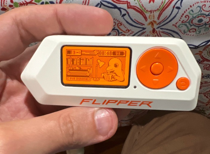
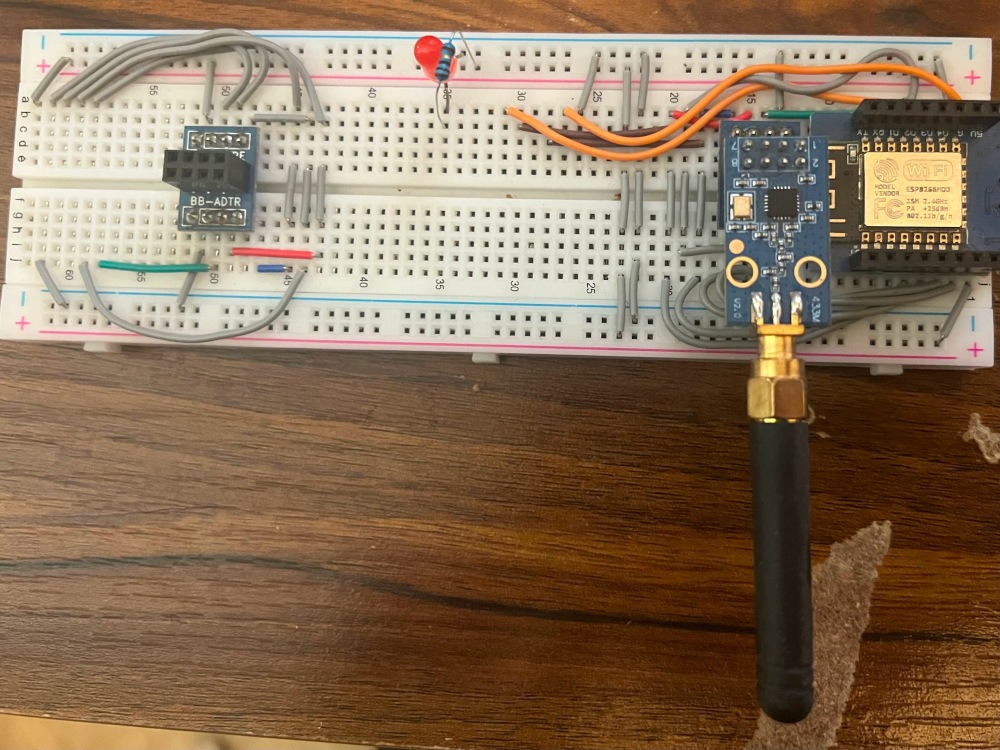
From there, I realized that the Flipper Zero is essentially an Arduino hooked up to a software defined radio called the CC1101. I could purchase two of these radios for under $10 and then fit one of them with an ESP8266 which I already had on hand to develop my solution.
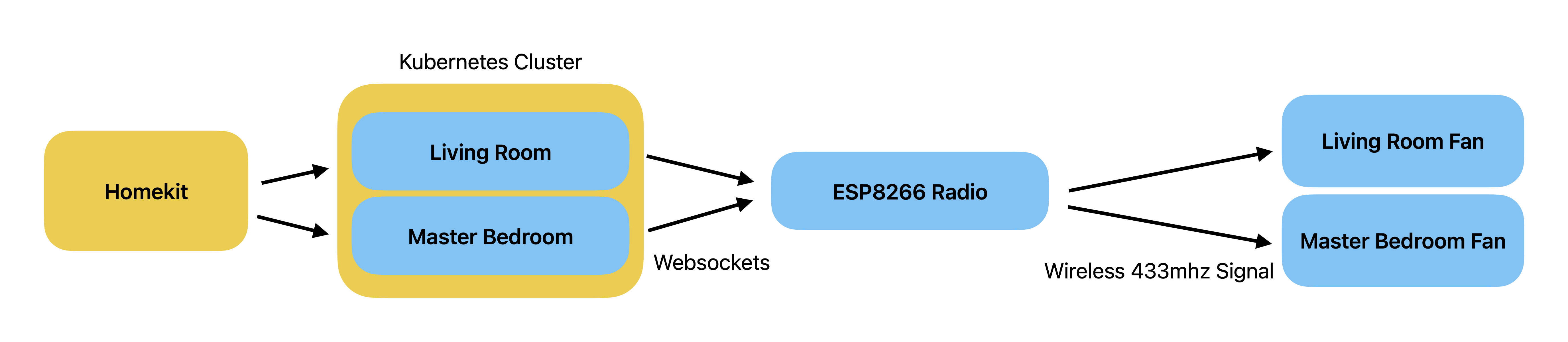
In my design I decided on a couple of things. The first was that since I was using an ESP8266 and had two fans to control; it would be ideal for the radio to be generic and just play any file sent to it over a web socket. This gave me two advantages. The second one was that memory would not be wasted handling HomeKit on the ESP8266.
This meant that I got to put my Kuberenetes cluster to work! (Don’t ask, just know that each Light gets its own Deployment in a Kubernetes cluster…. That runs on a Raspberry Pi… and is rendering this blog….
This design set me up for success from the hardware side because I only needed to focus on a very simple thing to have arbitrary control over anything. However, In order for my firmware to work I had to understand the FlipperZero’s file formats. I chose to go with their analog recording format mainly due to the simplicity of the file, and because there was already an ESP32 project that could play recorded files from SD card (here). A recorded analog file looks like the following
<Begin Incoherent Nerdy Rambling>
Filetype: Flipper SubGhz RAW File
Version: 1
Frequency: 433920000
Preset: FuriHalSubGhzPresetOok650Async
Protocol: RAW
RAW_Data: 24641 -68 141923 -1230 399 -1200 1169 -422 405 -1202 1203 -384 415 -1210 1167 -428 367 -1218 393 -1228 357 -1230 1179 -416 389 -1202 1209 -418 1173 -418 387 -1210 383 -1210 385 -1212 417 -1182 385 -1214 385 -1236 383 -1216 385 -1216 1179 -416 1187 -410 397 -1218 375 -1216 379 -1214 415 -1176 415 -1178 1213 -388 411 -1210 1179 -416 415 -11932 427 -1186 387 -1218 1179 -420 393 -1186 1211 -418 389 -1186 1205 -408 397 -1182 447 -1178 415 -1178 1213 -388 407 -1198 1211 -382 1211 -380 419 -1180 423 -1210 387 -1214 387 -1212 385 -1182 421 -1214 385 -1212 387 -1214 1199 -400 1185 -404 395 -1226 389 -1202 387 -1204 383 -1206 413 -1202 1209 -380 411 -1202 1181 -416 399 -11942 439 -1180 397 -1188 1217 -374 415 -1194 1217 -384 419 -1182 1199 -406 397 -1192 391 -1198 419 -1202 1211 -384 409 -1204 1209 -380 1205 -378 413 -1196 429 -1186 403 -1200 411 -1166 417 -1196 415 -1202 387 -1216 385 -1214 1187 -386 1217 -382 413 -1204 417 -1186 385 -1216 383 -1214 411 -1172 1197 -410 393 -1198 1213 -382 409 -11942 423 -1178 415 -1200 1181 -384 417 -1214 1185 -386 417 -1210 1167 -416 417 -1184 417 -1186 417 -1182 1185 -416 383 -1218 1183 -414 1183 -416 375 -1218 395 -1192 391 -1232 389 -1200 389 -1204 387 -1202 385 -1242 381 -1202 1177 -410 1183 -450 369 -1212 389 -1216 387 -1214 385 -1216 385 -1198 1183 -416 399 -1214 1179 -410 397 -11942 415 -1178 415 -1174 1203 -420 385 -1212 1207 -392 387 -1216 1209 -386 387 -1210 385 -1214 385 -1212 1209 -386 389 -1214 1209 -418 1183 -386 389 -1202 415 -1196 405 -1214 377 -1214 413 -1178 413 -1180 415 -1210 383 -1208 1183 -416 1177 -416 415 -1178 417 -1210 385 -1216 383 -1216 383 -1214 1183 -384 415 -1214 1183 -384 417 -148082 199 -694 65 -3614 899 -264 165 -66 231 -164 165 -66 563 -166 165 -632 397 -66 1255
This file format is easy to understand once you know the rules. The most important section is “RAW_Data”. This tells you how to create the waveform by storing how long to either turn the radio on or off in microseconds. To play this you split Raw_Data on spaces and then loop over that array. When you encounter a positive integer you set the radio pin high then sleep for that number of microseconds. When you encounter a negative integer you set the pin low and sleep for that (number of microseconds * -1).
</End Incoherent Nerdy Rambling>
Armed with this knowledge I wrote my Arduino code and was able to build a POC that could control my lights from Postman!
The great news for me at this point was I was no longer in unknown territory and into areas I specialize in.
The final step was to build Python code to handle HomeKit integration and track status of the lights. I chose to deploy this part as Kuberenetes containers that would run on my Raspberry Pi cluster. This was mainly due to the fact that I had the Pi Cluster, but it had nothing to do. I don’t want to get into too much detail about the code as that mostly speaks for itself. However, what this piece does is it listens for events from HomeKit and handles sending the correct file to the Arduino over the web socket.
The Astute reading this will realize that while my solution will work it’s not without caveats and there are two of them to mention in this design.
Before I explain here are pictures of the remotes. The living room remote is on the left and the master bedroom remote is on the right.
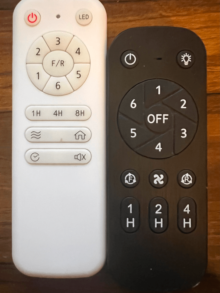
The first complication affects both my living room and my master bedroom lights. The problem is that the remote can control the lights without my python code knowing anything about it. What this means is that HomeKit could report that my lights or fans are on when they are really off or vice versa.
Thankfully, if you look at the remotes you will notice that each has an “All Off” power button. My python code sends this in any case where the expected outcome from HomeKit is that both Fan and Light should be off. What this means is that when either the fan or light is on and the user turns that device off the “All Off” signal is sent and HomeKit and the Fan will agree as the status will be all off. So to sync and know what is happening when I am away from my house I simply ensure that my actions will result in sending an “All Off” Command. For example; if I wish to turn off my bedroom lights and HomeKit reports they are on and that my fan is reported as off. I can simply toggle the lights off. In that case regardless of the fan’s actual status both the fan and light will be turned off.
The second complication only affects my living room and exists due to the crappiness of the remote interface itself. My living room fan has no separate power control button for the fan. In order to turn off the fan while leaving the light on a user must first turn off everything and then switch the light back on. From the python side this was easy to cope with, as I was able to simply automate this task when required to get full control of the fan via HomeKit.
To illustrate, if I have both the light and fan on and I turn off the fan in HomeKit. My HomeKit integration will send two commands instead of one. First, it will turn off everything. Next, after a half a second, it will send the command to turn the light back on. This enables decoupled control of the fan and light to the end user.
The results of this project were great for me. I got full control of the fans in my house via Siri. Found an excuse to purchase a Flipper Zero, and I learned a lot about the CC1101 and how to handle radio communication. In the future, I would love to learn more about how the Flipper manages things like rolling codes. That information will enable me to control my garage door with this radio and would also be very fun to build.
Note: As of writing, I do not know that this implementation is the best at this date. The original author of Homebridge-433 states that they moved to SignalDUINO. This new project may have supported my fans without issue. I would recommend looking at that first if you have a similar project in mind, unless you wish to build something weird!
Additional Notes: This project is really the result of gluing Arduino-433, and the Esp32-SubGhz projects together. These projects did not fit nicely on the ESP8266 and required some additional work to make everything function due to memory constraints.
Links and References.
I Adapted my Arduino code from the following sources
https://github.com/simondankelmann/Esp32-SubGhz
https://github.com/normen/homebridge-433-arduino
Here is a link to my code for the Arduino
https://gitlab.com/iot-hacking/flipper-radio-blaster
Here is the link to the code that hooks HomeKit with the Arduino for both rooms
https://gitlab.com/iot-hacking/rf-homekit
Stay Tuned, in Part 2 where we get EXTRA stupid!